Create an orthomosaic in Agisoft
Orthomosiac Guide
Written by Ben Weinstein, September 13, 2022
The goal of this wiki is to document the steps to create a Orthomosaic from a set of UAV raw images. This relates to the everglades project with both Inspire Quadcopter and Wingtra Drones, but can serve as a general guide for the steps to create a georeferenced image.
Agisoft
This tutorial uses Agisoft Metashape Pro. Future work needs to determine whether the standard version will suffice. We are following the manual here: https://www.agisoft.com/pdf/metashape-pro_1_7_en.pdf This tutorial is quick and dirty in the sense that we are choosing low quality outputs to speed up the workflow.
Load Images
Raw images look like:
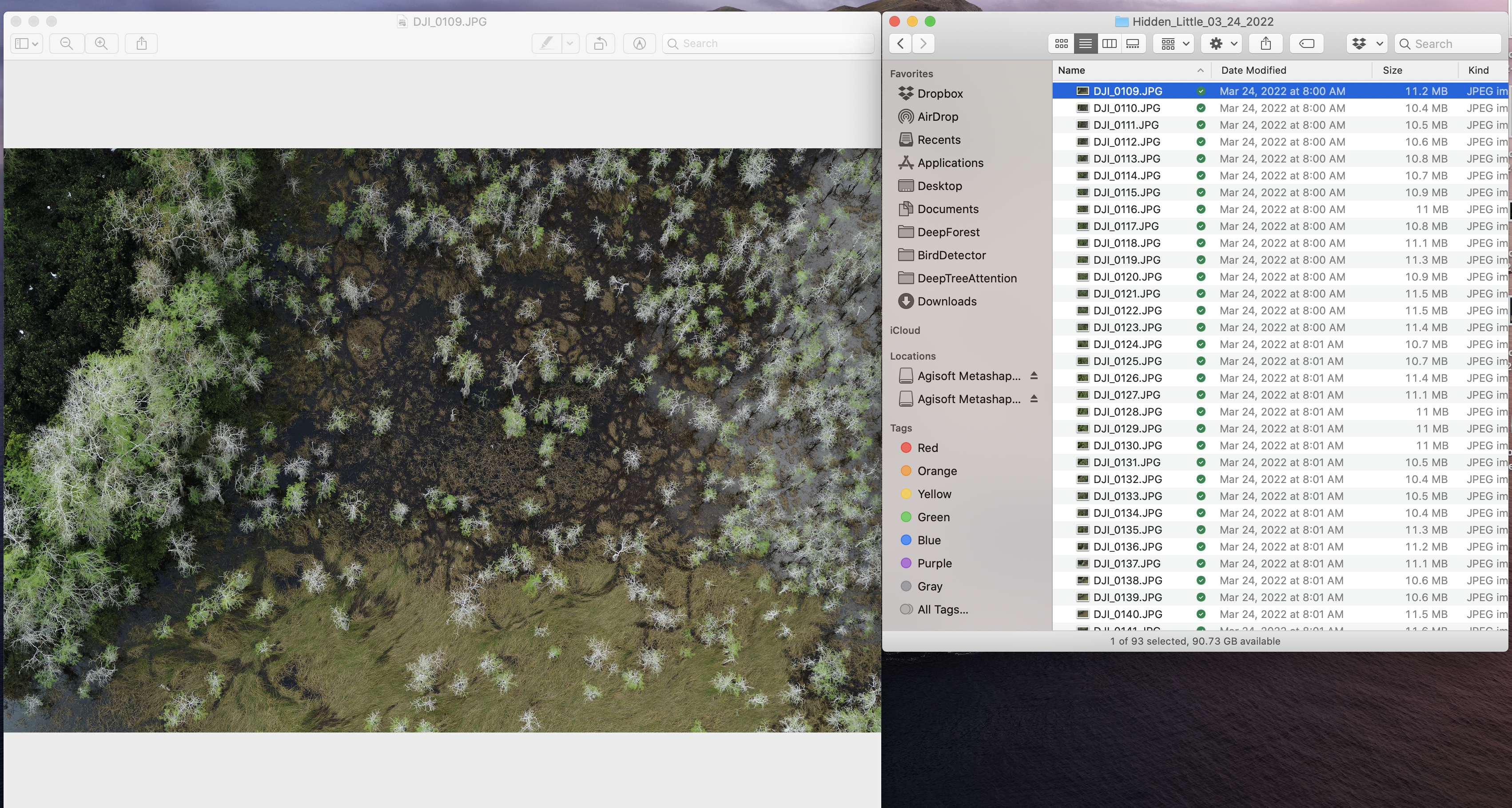
Workflow -> Add Folder

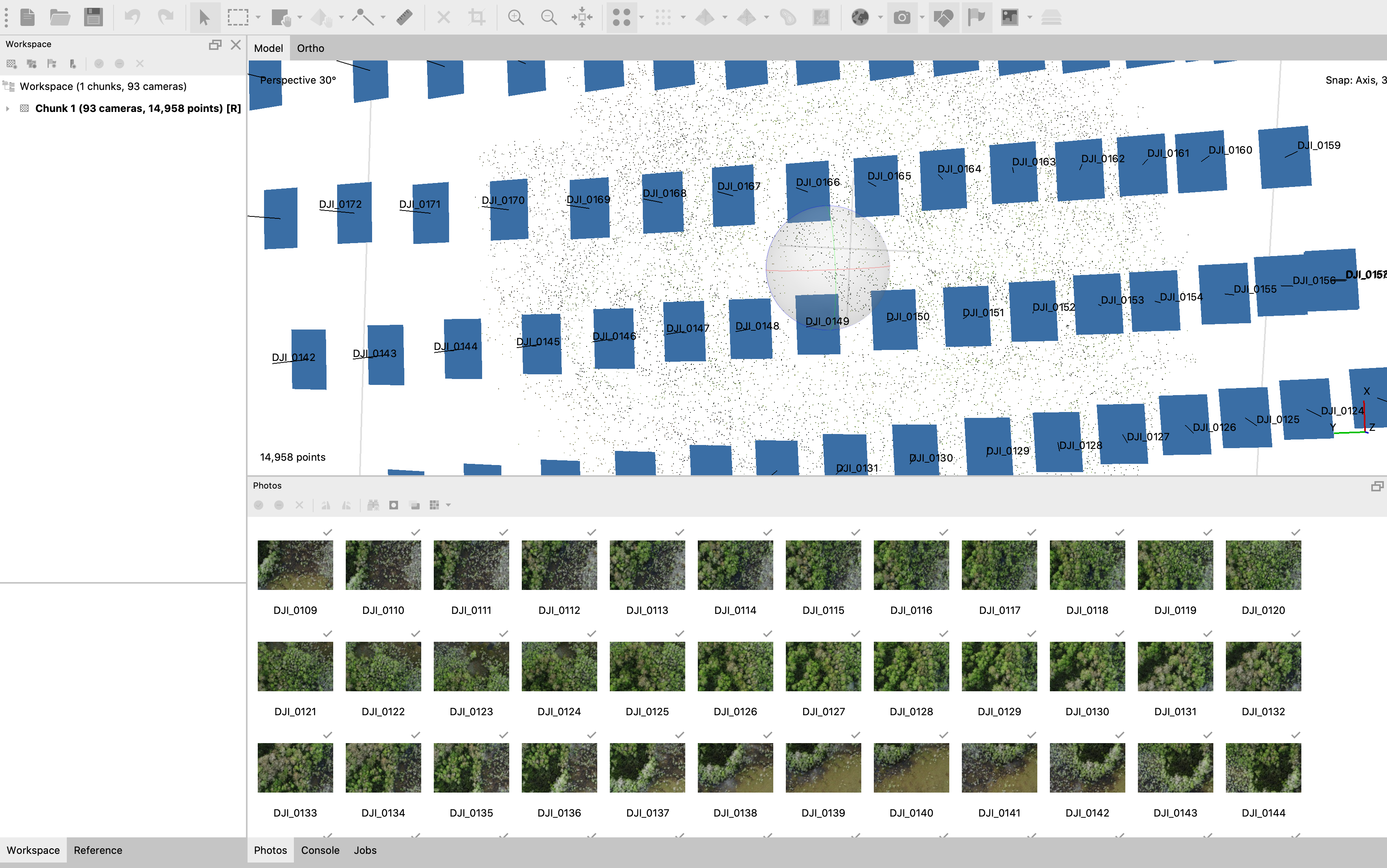
Align Photos
Align photos places the images from a single physical camera into a common reference system. It creates a sparse point cloud of overlap to generally tell where the images are in space.
To view the coordinate system and alignment, view the ‘reference’ tab in the bottom left.
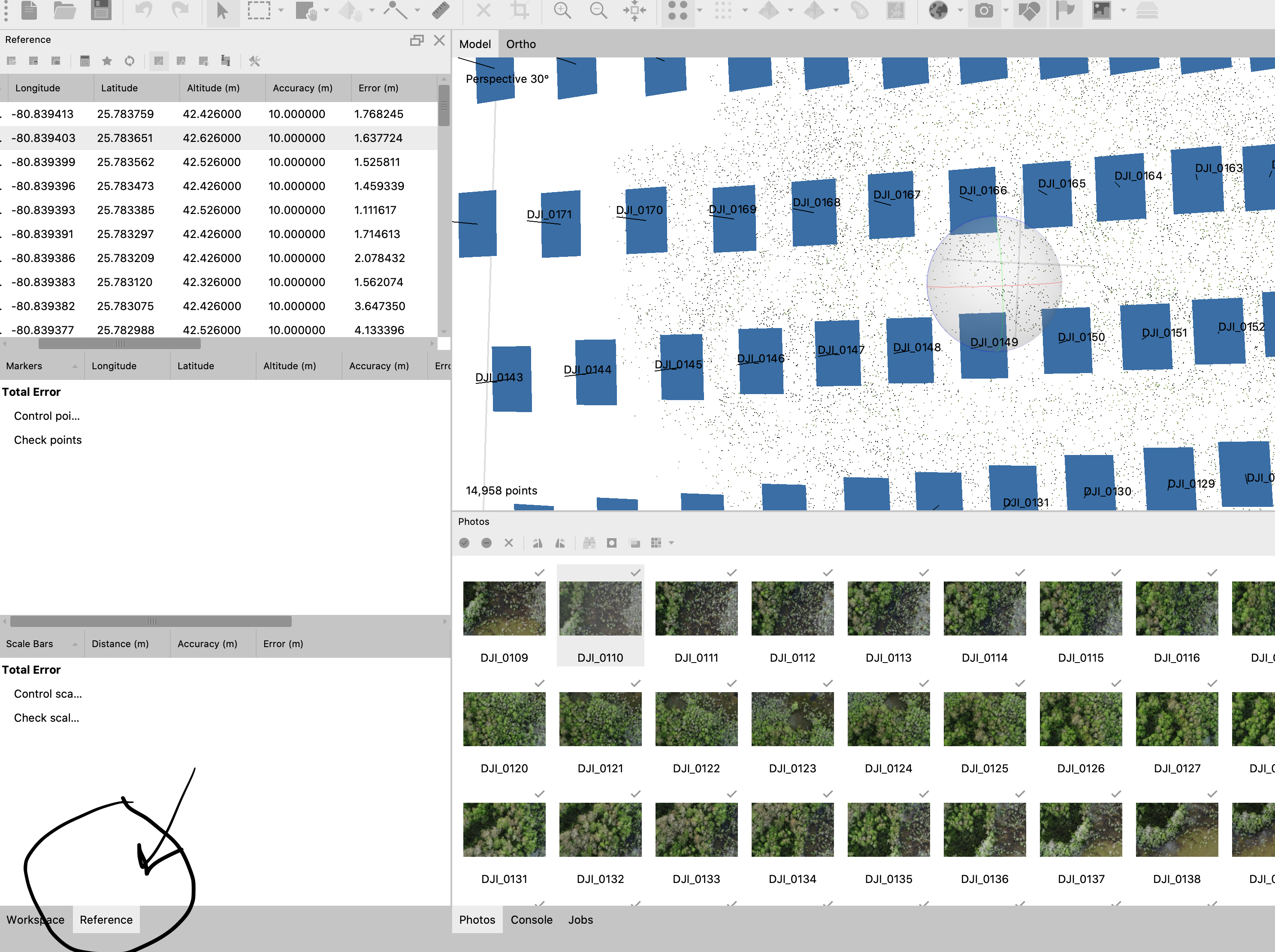
Set Coordinate Reference System
We are confident that the Inspire knows its geospatial accuracy to about 10m, and the pitch degree to about 1m.

Set Marker Points
If we don’t have ground control points we can skip this step.
Build Dense Cloud
Workflow -> Build Dense Cloud
The dense point cloud is required to build an elevation model to convert the 2D images into a 3d surface.
Build Digital Elevation Model
The elevation model projects the images into 3D space and is saved as a seperate .tif file.
Workflow -> Build DEM
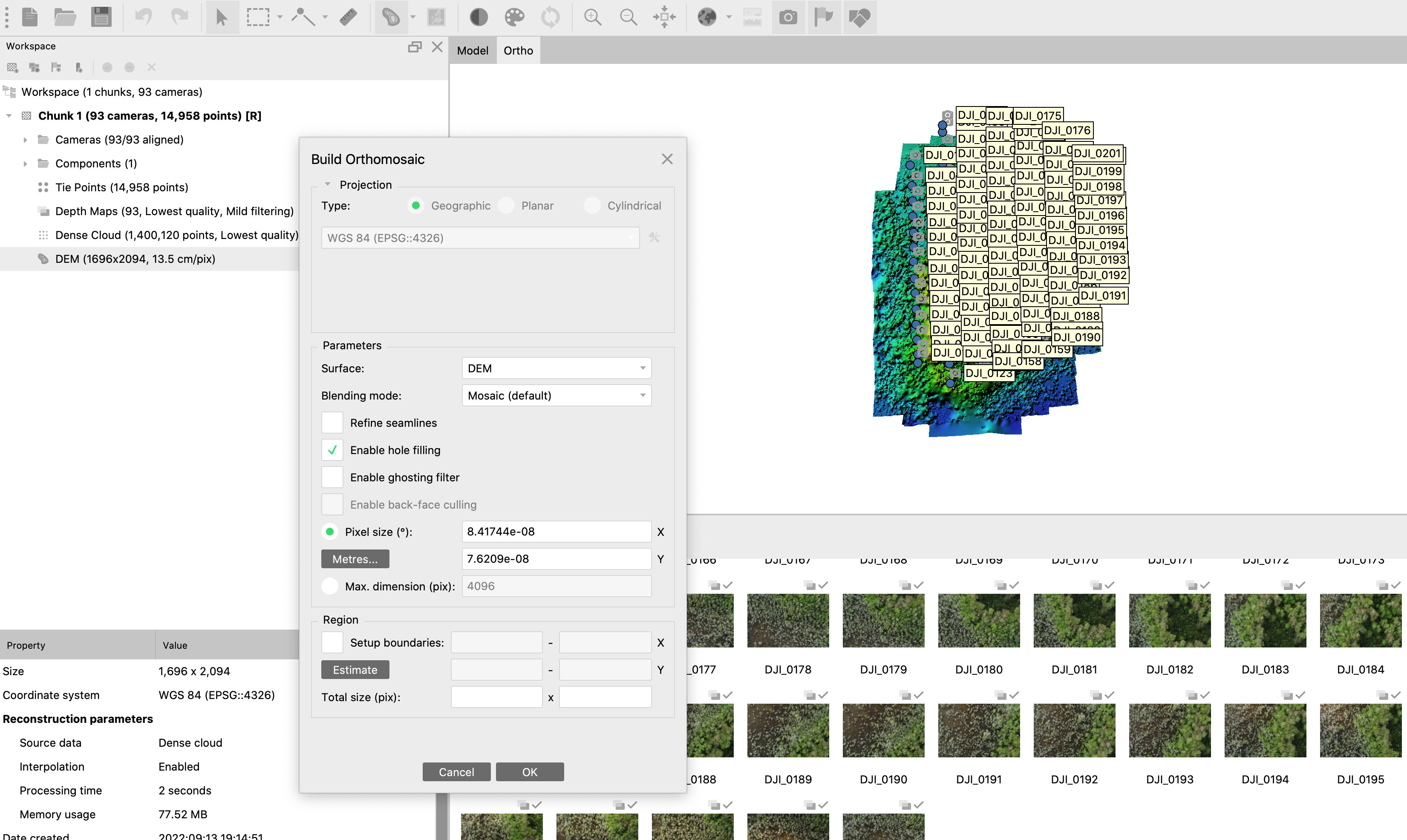
Build Orthomosaic
Use the digital elevation model and the dense point cloud to create a single stitched model of the entire colony.